
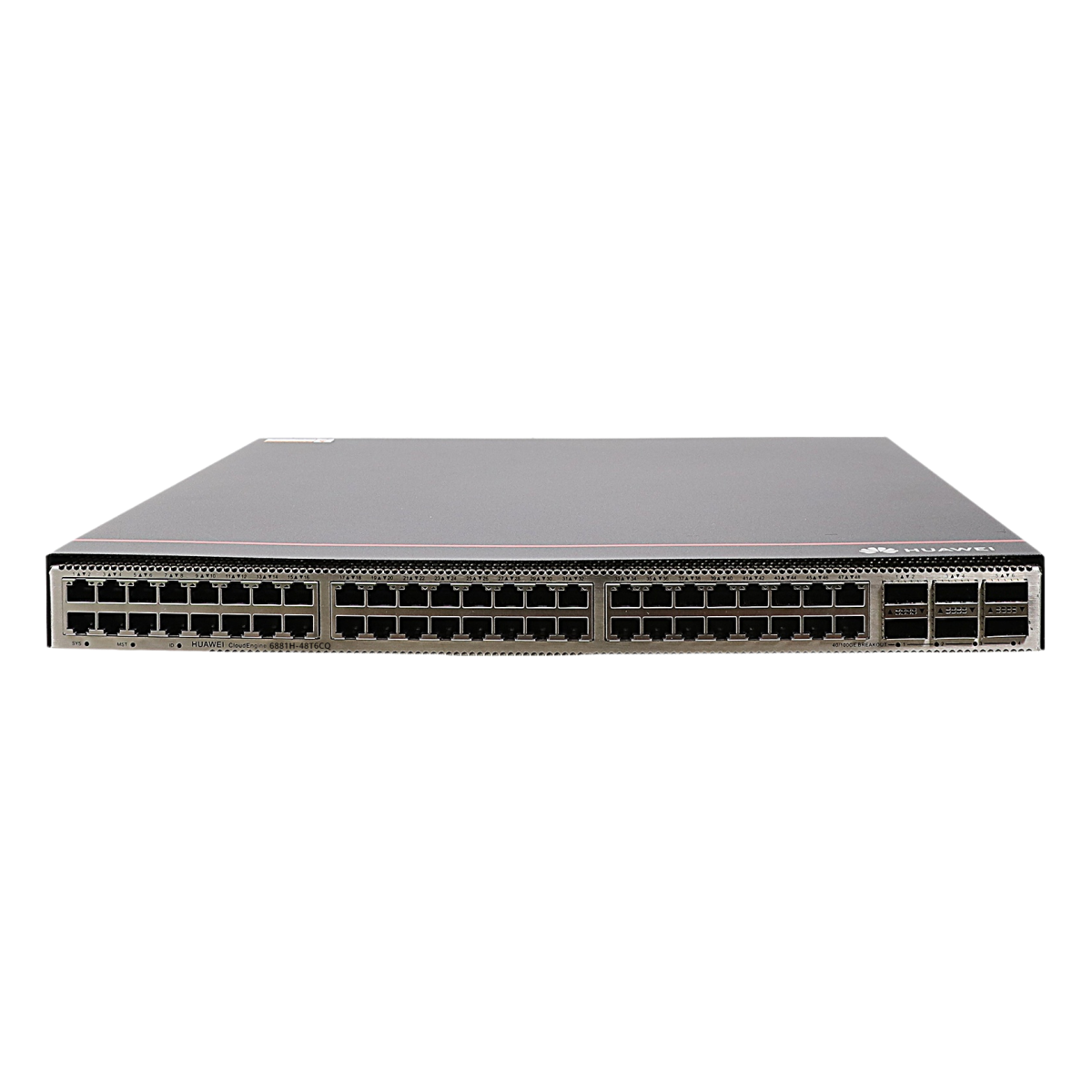
CE6881H-48T6CQ switch (48*10GE RJ45, 6*100GE QSFP28, without fan and power modules)
Condition: NOB
RMA Warranty

Description
Offering high-performance, high port density, and low latency, CloudEngine 6800 series switches enable enterprises and carriers alike to build cloud-oriented data center networks. The series features an advanced hardware design combined with either 10 GE, 25 GE, or 50 GE access ports, and 40 GE, 100 GE, or 200 GE uplink ports. Advanced data center features, high-performance stacking technologies, and flexible airflow capabilities complete the series. CloudEngine 6800 is well-suited to both the core and aggregation layers, and is fully compatible with CloudEngine 16800 and 12800 series switches, enabling enterprises to build scalable, simplified, open, and secure networks.
| Basic Information | |
| Description | CE6881H-48T6CQ switch (48*10GE RJ45, 6*100GE QSFP28, without fan and power modules) |
| Part Number | 02354VNR |
| Model | CE6881H-48T6CQ |
| First supported version | V300R022C00 |
| Other part numbers | 02354VNS (CE6881H-48T6CQ switch (48*10GE SFP+, 6*100GE QSFP28, 2*AC power modules, 4*fan modules, port-side intake)) 02354VNT (CE6881H-48T6CQ switch (48*10GE SFP+, 6*100GE QSFP28, 2*AC power modules, 4*fan modules, port-side exhaust)) |
| Short Name | CE6881H |
| Technical Specifications | |
| Dimensions with packaging (H x W x D) [mm (in.)] | 175 mm x 650 mm x 550 mm (6.89 in. x 25.59 in. x 21.65 in.) |
| Dimensions without packaging (H x W x D) [mm (in.)] | – Basic dimensions (the depth excludes the parts protruding from the body): 43.6 mm x 442.0 mm x 420.0 mm (1.72 in. x 17.40 in. x 16.54 in.) – Maximum dimensions (the depth is the distance from ports on the front panel to the parts protruding from the rear panel): 43.6 mm x 442.0 mm x 446.1 mm (1.72 in. x 17.40 in. x 17.56 in.) |
| Weight without packaging [kg (lb)] | 6.6 kg (14.55 lb) (excluding optical modules, power modules, and fan modules) |
| Weight without packaging (full configuration) [kg (lb)] | 8.9 kg (19.62 lb) (including AC power modules and fan modules, but not including optical modules. If the device supports multiple models of modules, the heaviest modules are used for the measurement.) |
| Weight with packaging [kg (lb)] | 10.4 kg (22.93 lb) |
| Weight with packaging (full configuration) [kg (lb)] | 12.3 kg (27.12 lb) |
| Chassis height [U] | 1 |
| Installation Type | Cabinet installation |
| Switching capacity | To obtain data of this specification item, see the corresponding datasheet or contact the product sales personnel. |
| CPU | Quad-core, 1.4 GHz |
| Memory | DRAM: 4 GB |
| NOR Flash | 64 MB |
| NAND Flash | 4 GB |
| USB | It can be used for log backup and USB-based deployment. This function is reserved. |
| Power supply mode | AC,DC,HVDC |
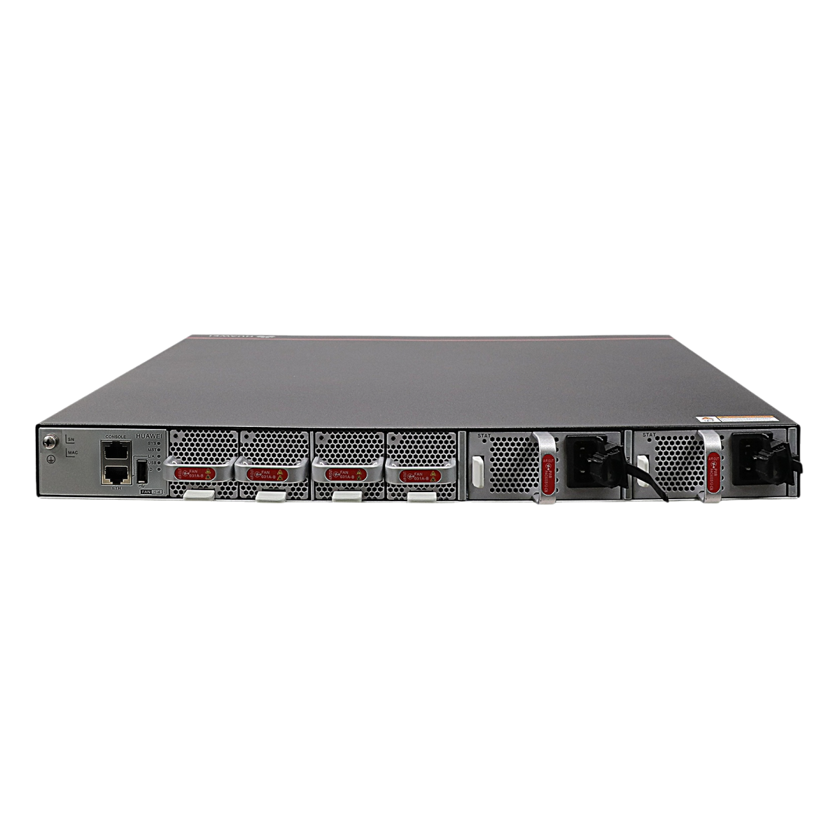
| Console port | RJ45 |
| Downlink Service interface | 48*10GE RJ45 (supporting only full-duplex) |
| Uplink Service interface | 6*100GE QSFP28 Note: 1. Each 100GE QSFP28 port can be used as a 40GE port. 2. A 100GE QSFP28 port cannot be split into 4x25GE and 4x10GE ports. 3. 100GE and 40GE 1 m/3 m/5 m copper cables are supported, and auto-negotiation of copper cables is not supported. 100GE and 40GE copper cables can only be used on M-LAG peer-link ports. When 100GE 3 m/5 m copper cables are used on such ports, these cables must work in the RS FEC mode. If they work in the non-RS FEC mode, the ports are in error-down state. |
| Service port supporting the stack function | Reserved function. This function is not enabled. |
| RTC | Supported |
| Typical power consumption [W] | – 347 W (50% throughput, 3 m Ethernet cables on 48 ports and QSFP28 high-speed cables on 6 ports, normal temperature, dual power modules) – 362 W (50% throughput, 3 m Ethernet cables on 48 ports and short-distance optical modules on 6 ports, normal temperature, dual power modules) |
| Typical heat dissipation [BTU/hour] | – 1184 BTU/hour (50% throughput, 3 m Ethernet cables on 48 ports and QSFP28 high-speed cables on 6 ports, normal temperature, dual power modules) – 1235 BTU/hour (50% throughput, 3 m Ethernet cables on 48 ports and short-distance optical modules on 6 ports, normal temperature, dual power modules) |
| Static power consumption [W] | 235 W |
| Static heat dissipation [BTU/hour] | 801 BTU/hour |
| Maximum power consumption [W] | 452 W |
| Maximum heat dissipation [BTU/hour] | 1542 BTU/hour |
| Number of power modules | 2 |
| Redundant power supply | 1+1 backup |
| Rated input voltage [V] | – 600 W AC&240 V DC power module: 100 V AC to 240 V AC, 50/60 Hz; 240 V DC – 1000 W DC power module: –48 V DC to –60 V DC – 1200 W high-voltage DC power module: 240 V DC to 380 V DC |
| Input voltage range [V] | – 600 W AC&240 V DC power module: 90 V AC to 290 V AC, 45 Hz to 65 Hz; 190 V DC to 290 V DC – 1000 W DC power module: –38.4 V DC to –72 V DC – 1200 W high-voltage DC power module: 190 V DC to 400 V DC |
| Maximum input current [A] | – 600 W AC&240 V DC power module: 8 A (100 V AC to 240 V AC); 4 A (240 V DC) – 1000 W DC power module: 30 A (–48 V DC to –60 V DC) – 1200 W high-voltage DC power module: 8 A |
| Rated output power [W] | – 600 W AC&240 V DC power module: 600 W – 1000 W DC power module: 1000 W – 1200 W high-voltage DC power module: 1200 W |
| Certification | – Compliance with safety standards – Compliance with EMC standards – Compliance with environment and environmental protection standards |
| Power supply surge protection [kV] | – AC: 6 kV in common mode and 6 kV in differential mode – DC: 4 kV in common mode and 2 kV in differential mode – HVDC: 4 kV in common mode and 2 kV in differential mode |
| Types of fans | Pluggable |
| Number of fans | 4 |
| Redundant fans | The device supports 3+1 backup of fan modules that work in hot standby mode. The system can operate properly for a short period of time after a single fan module fails. You are advised to replace the faulty fan module immediately. |
| Heat dissipation mode | Air cooling |
| Airflow direction | Front-to-back or back-to-front airflow, depending on the selected fan modules and power modules |
| Availability | 0.9999953209 |
| MTBF [year] | 48.16 years |
| MTTR [hour] | 1.78 hours |
| Noise at normal temperature (27°C, sound pressure) [dB(A)] | – Front-to-back airflow: 49 dB(A) on average (maximum: 52 dB(A)) – Back-to-front airflow: 50 dB(A) on average (maximum: 52 dB(A)) |
| Noise at high temperature (40°C, sound pressure) [dB(A)] | – Front-to-back airflow: 69 dB(A) on average (maximum: 74 dB(A)) – Back-to-front airflow: 67 dB(A) on average (maximum: 73 dB(A)) |
| Long-term operating altitude [m (ft.)] | ≤ 5000 m (16404 ft.) |
| Long-term operating relative humidity [RH] | 5% RH to 95% RH, non-condensing |
| Long-term operating temperature [°C (°F)] | 0°C to 40°C (32°F to 104°F) at an altitude of 0–1800 m (0–5906 ft.) Note: When the altitude is 1800–5000 m (5096–16404 ft.), the highest operating temperature reduces by 1°C (1.8°F) every time the altitude increases by 220 m (722 ft.). |
| Storage altitude [m (ft.)] | ≤ 5000 m (16404 ft.) |
| Storage relative humidity [RH] | 5% to 95% RH, non-condensing |
| Storage temperature [°C (°F)] | -40ºC to +70ºC (-40°F to +158°F) |
| Ethernet Switching>Eth-Trunk | |
| IEEE 802.3ad | Y |
| Ethernet Switching>STP/RSTP/MSTP | |
| Loop prevention | Y |
| IEEE 802.1w(RSTP) | Y |
| IEEE 802.1s(MSTP) | Y |
| Root protection | Y |
| BPDU protection | Y |
| IEEE 802.1d (STP) | Y |
| Ethernet Switching>VBST>VBST function | |
| VBST | Y |
| Ethernet Switching>VLAN>VLAN Basics>Port Link Type | |
| access | Y |
| hybrid | Y |
| trunk | Y |
| IP address and service>ARP Security | |
| Interface-based ARP packet suppression | Y |
| QoS>Congestion Management>Congestion Management>Scheduling management | |
| Queue scheduling algorithm | Y |
| QoS>MQC>Re-marking | |
| Re-marking DSCP values of packets | Y |
| Re-marking outer 802.1p priorities of packets | Y |
| QoS>Re-marking | |
| Re-marking DSCP values of packets | Y |
| Re-marking outer 802.1p priorities of packets | Y |
| QoS>Traffic Policing, Traffic Shaping, and Interface-based Rate Limiting>Traffic Shaping>Interface-based Rate Limiting | |
| Configuring outbound interface-based rate limiting on an interface | Y |
| QoS>Traffic Policing, Traffic Shaping, and Interface-based Rate Limiting>Traffic Shaping>Queue shaping | |
| Configuring queue shaping on an interface | Y |
| Reliability>BFD>BFD Service Scenario>BFD for M-LAG | |
| BFDv6 for M-LAG | Y |
| BFD for M-LAG | Y |
| Reliability>BFD>BFD Service Scenario>BFD session | |
| BFD session performance of a board (when the minimum detection period is configured) | 128 (3 ms x 3) |
| Number of BFD sessions in the system | 1024 |
| Default interval at which BFD packets are sent and received | 1000 ms |
| Reliability>M-LAG>Common mechanism | |
| Maintenance mode | Y |
| M-LAG function | Y |
| Reliability>VRRP | |
| VRRP group | 1024 |
| Security>Local Attack Defense>ARPSec>ARP packet rate limiting | |
| Interface-based ARP packet suppression | Y |
| Security>Local Attack Defense>ICMP Security | |
| ICMP Security-Abnormal Packet Detection | Y |
| Security>Port Security | |
| Port security | Y |
| Security>Storm Suppression>Storm Control | |
| Storm control for unknown multicast packets on an interface | Y |
| Storm control for unknown unicast packets on an interface | Y |
| Storm control for broadcast packets on an interface | Y |
| Security>Storm Suppression>Traffic Suppression | |
| Broadcast storm suppression in a BD | Y |
| Broadcast traffic suppression in a VLAN | Y |
| Multicast traffic suppression in a VLAN | Y |
| System Management>Hardware management>Device Management>Board management>Device restart | |
| Device restart | Y |
| System Monitoring>Mirroring | |
| N:1 mirroring | Y |
| 1:N mirroring | Y |
| Inbound port mirroring | Y |
| Flow mirroring | Y |
| Outbound port mirroring | Y |
| System Monitoring>NetStream>NetStream>Flexible flow | |
| Creating IPv4 flexible flows | Y |
| Creating IPv6 flexible flows | Y |
| Creating IPv4 over IPv4 VXLAN flexible flows | Y |
| System Monitoring>NetStream>NetStream>Original flow | |
| Creating IPv4 original flows | Y |
| Creating IPv6 original flows | Y |
| System Monitoring>NetStream>NetStream>Statistics export | |
| Exporting packets carrying IPv4 flexible flow statistics | Y |
| Exporting packets carrying IPv4 original flow statistics in V5 format | Y |
| Exporting packets carrying IPv4 original flow statistics in V9 format | Y |
| Exporting packets carrying IPv6 original flow statistics in V9 format | Y |
| Exporting packets carrying IPv6 flexible flow statistics | Y |
| System Monitoring>NetStream>NetStream>Traffic sampling | |
| Sampling on Eth-Trunk interfaces | Y |
| Data flows can be sampled based on inbound and outbound interfaces. | Y |
| Sampling on Layer 2 sub-interfaces | Y |
| Sampling on Layer 3 sub-interfaces | Y |
| Sampling on physical interfaces | Y |
| System Monitoring>Packet Event>Packet loss visualization | |
| Visualization of statistics about packets discarded due to forwarding exceptions | Y |
| Configuring packet loss visualization for RoCEv2 packets so that the device can create flow entries for RoCEv2 packets and send the flow entries to the analyzer | Y |
| License control items | Y |
| Visualization of statistics about packets that are discarded normally | Y |
| System Monitoring>Telemetry>Telemetry Service>Static Telemetry Configuration | |
| Combination and sending of sampled data in subscription | 1. By default, the sampled data of different sampling paths is sent to the collector separately. The packet combination function combines the sampled data together and sends it to the collector. In this way, the distributed data sending mode is changed to the centralized data sending mode. 2. Packet combination is to combine the sampled data in a sampling period and send the data together. Therefore, packet combination period is the same as the sampling period. If a subscription has multiple sampling periods, the maximum sampling period is configured as the packet combination period. If all sampling periods are 0, the packet combination period is 1s. 3. If the accumulated data reaches 80 KB in the packet combination period, the data is sent immediately. 4. The variable frequency sampling period of telemetry does not affect the packet combination period. 5. The packet combination function and the UDP protocol are mutually exclusive. |
| User Access and Authentication>AAA>Authentication Management>Authentication Management | |
| RADIUS authentication method | Y |
| HWTACACS authentication method | Y |
| User Access and Authentication>AAA>Domain management>Domain management | |
| Domain management | Y |
| User Access and Authentication>AAA>Local user management>Administrator User Management | |
| Configuring local account attributes | Y |
| User Access and Authentication>AAA>RADIUS management>RADIUS authentication | |
| Configuring a primary authentication server | Y |
| VXLAN>VXLAN>Configuring ARP and VXLAN together>BUM flooding | |
| ARP broadcast-to-unicast conversion | Y |
| VXLAN>VXLAN>Configuring IPv6 and VXLAN together>Layer 3 gateway | |
| IPv6 over VXLANv6 Layer 3 gateway | Y |
| VXLAN>VXLAN>Segment VXLAN>DCI | |
| Segment VXLAN implementing Layer 3 communication | Y |
| Segment VXLAN implements Layer 2 communication. | Y |
| Segment VXLANv6 implementing Layer 2 communication | Y |
| Segment VXLANv6 implementing Layer 3 communication | Y |
| VXLAN>VXLAN>VXLAN Service>BUM flooding | |
| ARP broadcast-to-unicast conversion | Y |
| VXLAN>VXLAN>VXLAN tunnel>BGP EVPN | |
| IBGP EVPN and EBGP EVPN on the VXLAN control plane | Y |

John (verified owner) –
The product is firmly packed.